Visualização normal

Antes de ontemStream principal
  • ✇Securelist
  • PhantomRPC: A new privilege escalation technique in Windows RPC Haidar Kabibo
    Intro Windows Interprocess Communication (IPC) is one of the most complex technologies within the Windows operating system. At the core of this ecosystem is the Remote Procedure Call (RPC) mechanism, which can function as a standalone communication channel or as the underlying transport layer for more advanced interprocess communication technologies. Because of its complexity and widespread use, RPC has historically been a rich source of security issues. Over the years, researchers have identifi
     

PhantomRPC: A new privilege escalation technique in Windows RPC

24 de Abril de 2026, 05:00

Intro

Windows Interprocess Communication (IPC) is one of the most complex technologies within the Windows operating system. At the core of this ecosystem is the Remote Procedure Call (RPC) mechanism, which can function as a standalone communication channel or as the underlying transport layer for more advanced interprocess communication technologies. Because of its complexity and widespread use, RPC has historically been a rich source of security issues. Over the years, researchers have identified numerous vulnerabilities in services that rely on RPC, ranging from local privilege escalation to full remote code execution.

In this research, I present a new vulnerability in the RPC architecture that enables a novel local privilege escalation technique likely in all Windows versions. This technique enables processes with impersonation privileges to elevate their permissions to SYSTEM level. Although this vulnerability differs fundamentally from the “Potato” exploit family, Microsoft has not issued a patch despite proper disclosure.

I will demonstrate five different exploitation paths that show how privileges can be escalated from various local or network service contexts to SYSTEM or high-privileged users. Some techniques rely on coercion, some require user interaction and some take advantage of background services. As this issue stems from an architectural weakness, the number of potential attack vectors is effectively unlimited; any new process or service that depends on RPC could introduce another possible escalation path. For this reason, I also outline a methodology for identifying such opportunities.

Finally, I examine possible detection strategies, as well as defensive approaches that can help mitigate such attacks.

MSRPC

Microsoft RPC (Remote Procedure Call) is a Windows technology that enables communication between two processes. It enables one process to invoke functions that are implemented in another process, even though they are running in different execution contexts.

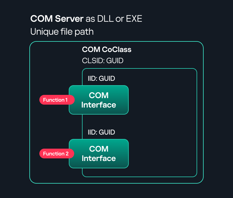
The figure below illustrates this mechanism.

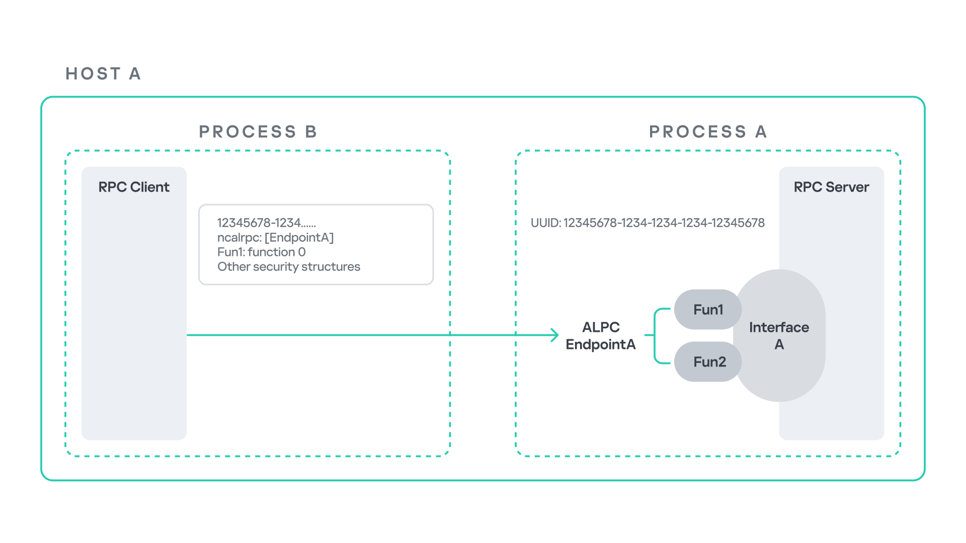
Let us assume that Host A is running two processes: Process A and Process B. Process B needs to execute a function that resides inside Process A. To enable this type of interaction, Windows provides the Remote Procedure Call (RPC) architecture, which follows a client–server model. In this model, Process A acts as the RPC server, exposing its functionality through an interface, in our example, Interface A. Each RPC interface is uniquely identified by a Universally Unique Identifier (UUID), which is represented as a 128-bit value. This identifier enables the operating system to distinguish one interface from another.

The interface defines a set of functions that can be invoked remotely by the RPC client implemented in Process B. In our example, the interface exposes two functions: Fun1 and Fun2.

To communicate with the server, the RPC client must establish a connection through a communication endpoint. An endpoint represents the access point that enables transport between the client and the server. Because RPC supports multiple transport mechanisms, different endpoint types may exist, depending on the underlying transport.

For example:

  • When TCP is used as the transport layer, the endpoint is a TCP port.
  • When SMB is used, communication occurs through a named pipe.
  • When ALPC is used, the endpoint is an ALPC port.

Each transport mechanism is associated with a specific RPC protocol sequence. For instance:

  • ncacn_ip_tcp is used for RPC over TCP.
  • ncacn_np is used for RPC over named pipes.
  • ncalrpc is used for RPC over ALPC.

In this research, I focus specifically on Advanced Local Procedure Call (ALPC) as the RPC transport mechanism. ALPC is a Windows interprocess communication mechanism that predates MSRPC. Today, RPC can leverage ALPC as an efficient transport layer for communication between processes located on the same machine.

For simplicity, an ALPC port can be thought of as a communication channel similar to a file, where processes can send messages by writing to it, and receive messages by reading from it.

When the client wants to invoke a remote function, for example, Fun1, it must construct an RPC request. This request includes several important pieces of information, such as the interface UUID, the protocol sequence, the endpoint, and the function identifier. In RPC, functions are not referenced by name, but by a numerical identifier called the operation number (OPNUM). Depending on the requirements of the call, the request may also contain additional structures, such as security-related information.

Impersonation in Windows

In Windows, impersonation enables a service to temporarily operate using another user’s security context. For example, a service may need to open a file that belongs to a user while performing a specific operation. By impersonating the calling user, the system allows the service to access that file, even if the service itself would not normally have permission to do so. You can read more about impersonation in James Forshaw’s book Windows Security Internals.

This research focuses specifically on RPC impersonation. Instead of describing the interaction as a service and a user, I refer to the participants as a client and a server. In this model, the RPC server may temporarily adopt the identity of the client that initiated the request.

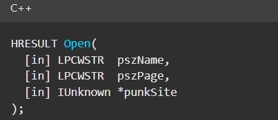
To perform this operation, the RPC server can call the RpcImpersonateClient API, which causes the server thread to execute under the client’s security context.

However, in some situations, a client may not want the server to be able to impersonate its identity. To control this behavior, Windows introduces the concept of an impersonation level. This defines how much authority the client grants the server to act on its behalf.

These settings are defined as part of the Security Quality of Service (SQOS) parameters, specified using the SECURITY_QUALITY_OF_SERVICE structure.

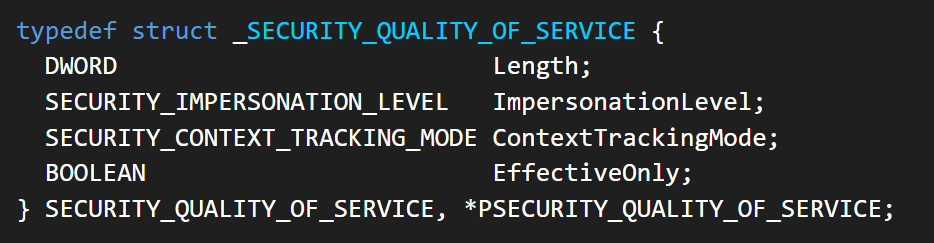
As you can see, this structure contains the impersonation level field, which determines the extent to which the server can assume the client’s identity.

Impersonation levels range from Anonymous, where the server cannot impersonate the client at all, to Impersonate and Delegate, which allow the server to act fully on behalf of the client.

At the same time, not every server process is allowed to impersonate a client. If any process could perform impersonation freely, it would pose a serious security risk. To prevent this, Windows requires the server process to possess a specific privilege called SeImpersonatePrivilege. Only processes with this privilege can successfully impersonate a client.

This privilege is granted by default to certain service accounts, such as Local Service and Network Service.

Interaction between Group Policy service and TermService

The Group Policy Client service (gpsvc) is a core Windows service responsible for applying and enforcing group policy settings on a system. It runs under the SYSTEM account inside svchost.exe.

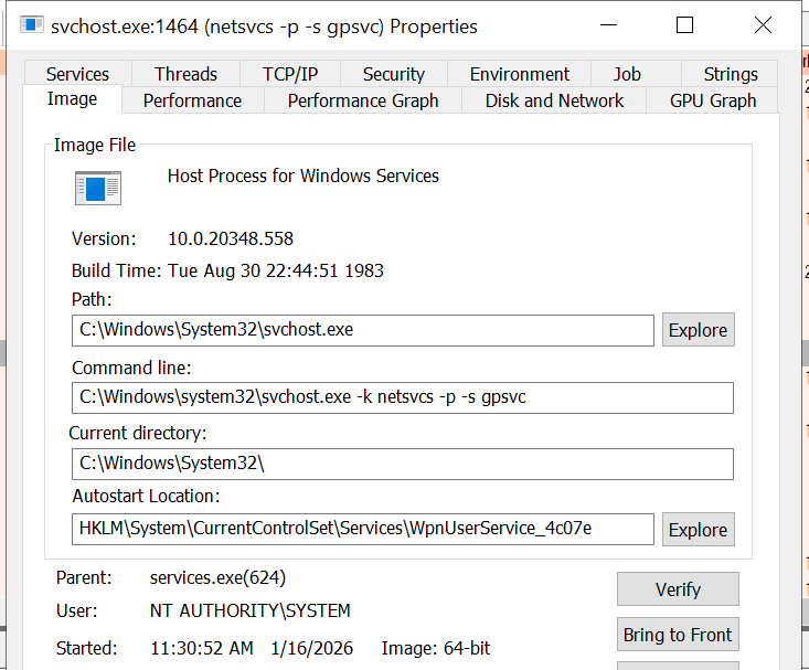
When a group policy update is triggered, Windows uses an executable called gpupdate.exe. This tool can be executed with the /force flag to force an immediate refresh of all group policy settings. Internally, this executable communicates with the Group Policy service, which coordinates the update process.

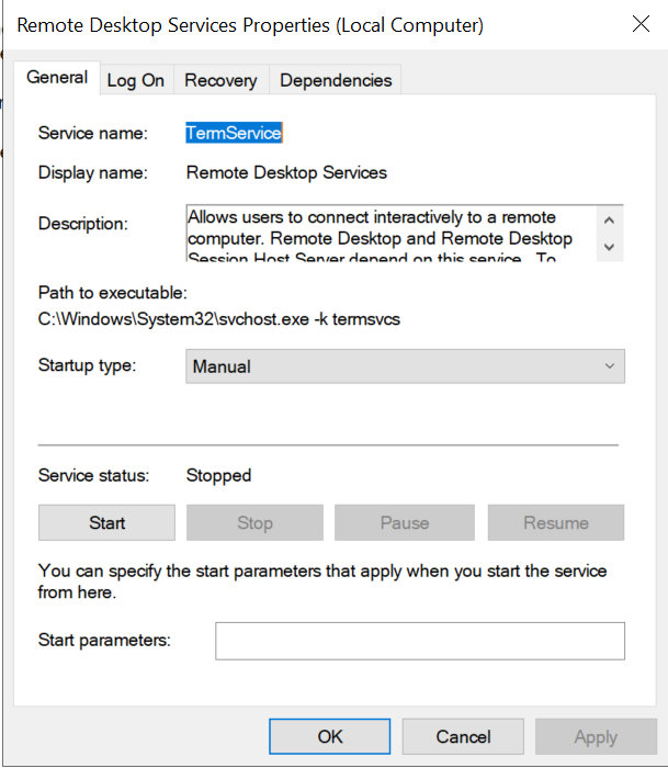
At a certain stage during this operation, the Group Policy service attempts to communicate with TermService (Terminal Service, the Remote Desktop Services service) using RPC.

TermService is responsible for providing remote desktop functionality. This service is not running by default and can be enabled manually by the administrator via activation of Remote Desktop access. When this happens, the service exposes an RPC server with multiple interfaces and endpoints. TermService runs under the NT AUTHORITY\Network Service account.

When the command gpupdate /force is executed, the Group Policy service performs an RPC call to the TermService using the following parameters:

  • UUID: bde95fdf-eee0-45de-9e12-e5a61cd0d4fe.
  • Endpoint: ncalrpc:[TermSrvApi].
  • Function: void Proc8(int).

However, because TermService is disabled by default, the RPC call fails and an exception occurs in rpcrt4.dll (the RPC runtime). The returned error is:

  • 0x800706BA (RPC_S_SERVER_UNAVAILABLE, 1722).

This error indicates that the RPC client could not reach the target server.

Tracing the failure path further reveals that the root cause originates from a call to NtAlpcConnectPort, which is used by RPC to establish an ALPC connection between processes.

The NtAlpcConnectPort function is responsible for connecting to a specific ALPC port and returning a handle that the client can use for further communication. This function accepts multiple parameters.

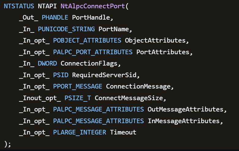
The first two parameters include:

  • A pointer to the returned port handle.
  • The ALPC port name, represented as an ASCII string.

Another important argument is PortAttributes, which is an ALPC_PORT_ATTRIBUTES structure. Inside this structure is the SECURITY_QUALITY_OF_SERVICE structure, which, as mentioned above, defines the impersonation level used for the connection.

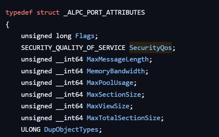
The final parameter of interest is RequiredServerSid, which specifies the expected identity of the target server process. This identity is represented using a Security Identifier (SID) structure.

Inspecting this call reveals that the Group Policy service attempts to connect to the RPC server using an impersonation level of Impersonate, expecting the remote server to run under the Network Service account. This behavior makes sense because TermService normally runs under Network Service.

Based on all the information above, the following scheme can be created to illustrate the interaction between TermService and gpsvc.

Up to this point, nothing unusual has occurred. An RPC client attempts to connect to an RPC server that is unavailable, resulting in an exception handled by the RPC runtime.

However, an interesting question arises: What if an attacker compromises a service that runs under the Network Service identity and mimics the exact RPC server exposed by TermService?

Could the attacker deploy a fake RPC server with the same endpoint?

If so, would the RPC runtime allow the client to connect to this illegitimate server?

And if the connection is successful, how could an attacker leverage this behavior?

Coercing the Group Policy service

To better understand the implications of the previously described behavior, let us consider the following attack scenario.

Imagine an attacker has compromised a service running on the system under the Network Service account, for example, an IIS server operating under the Network Service account. With this level of access, the attacker can deploy a malicious RPC server.

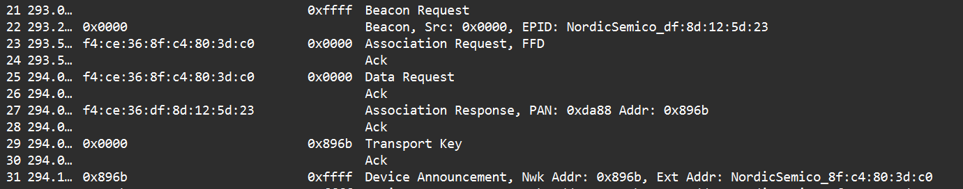
The attacker’s RPC server is designed to mimic the RPC interface exposed by the Remote Desktop service (TermService). Specifically, it implements the same RPC interface UUID and exposes the same endpoint name: TermSrvApi. Once deployed, the malicious server listens for RPC requests that would normally be directed to the legitimate RDP service.

Next, the attacker coerces the Group Policy service by triggering a policy update using gpupdate.exe /force. This causes the Group Policy Client service, which runs under the SYSTEM account, to perform the previously described RPC call. As observed earlier, this RPC call uses a high impersonation level (Impersonate).

When the attacker’s fake RPC server receives the request, it calls RpcImpersonateClient. This enables the server thread to impersonate the security context of the calling client, which, in this case, is SYSTEM.

As a result, the attacker can elevate privileges from Network Service to SYSTEM. In our proof-of-concept implementation, the exploit demonstrates privilege escalation by spawning a SYSTEM-level command prompt.

When this attack scenario was first discussed, it was purely theoretical. However, after implementing the malicious RPC server, the experiment confirmed that Windows allowed the server to be deployed and started successfully, and that the RPC runtime permitted the client to connect to the malicious endpoint. This made it possible to reliably escalate privileges from Network Service to SYSTEM using this technique. For this attack to succeed, though, at least one group policy must be applied on the system.

RPC architecture flow

Further investigation revealed that many Windows services attempt to communicate with TermService using RPC. These RPC calls often originate from winsta.dll, which acts as the RPC client component.

Windows processes invoke APIs exposed by winsta.dll; these APIs rely internally on RPC communication with TermService. This pattern is common in Windows; many system DLLs use RPC behind the scenes when their exported APIs are called.

However, it appears that the RPC runtime (rpcrt4.dll) does not provide a mechanism to verify the legitimacy of RPC servers. Moreover, Windows allows another process to deploy an RPC server that exposes the same endpoint as a legitimate service.

As a result, this architectural design introduces a large attack surface because RPC is heavily used across numerous system DLLs. Applications that invoke seemingly benign APIs may unintentionally trigger privileged RPC interactions. Under certain conditions, these interactions could be abused to achieve local privilege escalation without the user’s knowledge.

Identifying RPC calls to unavailable servers

As the issue appears to stem from an architectural weakness, a systematic approach is needed to identify RPC clients attempting to communicate with servers that are unavailable. First, I need a platform capable of monitoring RPC activity and extracting relevant information from each RPC request.

Specifically, I need to capture key RPC metadata, including:

  • Interface UUID, endpoint, and OPNUM.
  • Impersonation level and RPC status code.
  • Client process privilege level, process name, and module path.

This information is critical because it enables me to reconstruct the RPC interaction, mimic the expected RPC server, and determine how the call is triggered.

The platform that provides this capability is Event Tracing for Windows (ETW). ETW is a built-in Windows logging framework that captures both kernel-mode and user-mode events in real time.

Windows provides a tool called logman to collect ETW data. It enables us to create trace sessions, select event providers, and configure the verbosity level of the tracing process. The collected tracing data is stored in an .etl file, which can later be analyzed using tools such as Event Viewer or other ETW analysis utilities.

ETW provides deep visibility into RPC activity without requiring modifications to applications. Through ETW, it is possible to capture detailed RPC information, such as:

  • RPC bindings
  • Endpoints
  • Interface UUIDs
  • Authentication details
  • Call flow and timing
  • RPC status codes

However, I’m not interested in every RPC event. My focus is on RPC call failures, specifically those that return the status RPC_S_SERVER_UNAVAILABLE.

For an event to be relevant to this research, the exception must meet two conditions:

  • It must originate from a high-privileged process because impersonating such a process may allow an attacker to escalate privileges to a more powerful security context.
  • The RPC call must use a high impersonation level, enabling the server to fully impersonate the client once the connection is established.

I cannot rely solely on the raw ETW output to implement this framework because it contains thousands of events, making manual filtering with standard tools inefficient. Therefore, I need to automate this process. The workflow shown below enables me to efficiently filter and extract only those events that are relevant to this analysis.

After generating the logs as an .etl file, I convert them to JSON format using tools such as etw2json. JSON is a much easier format to process programmatically. In this case, I use a Python script to filter and extract the relevant information.

The filtering process begins with a search for Event ID 1, which corresponds to an RPC stop event. This event indicates that the RPC client has completed the call and the result is available. From this event, I can extract useful information, such as:

  • Status code
  • Client process name
  • Client process ID
  • Endpoint

After extracting the status code, I filter for the specific value RPC_S_SERVER_UNAVAILABLE, which indicates that the target server was unreachable during an RPC call. These events represent the scenarios that are of interest.

However, Event ID 1 does not contain all of the required RPC metadata. To obtain the missing information, it is correlated with Event ID 5, which represents the RPC start event. This event is generated when the client initiates the RPC call.

By matching the metadata between Event ID 1 and Event ID 5, I can recover the missing details, including:

  • Interface UUID
  • OPNUM
  • Impersonation level

After correlating and filtering these events, a JSON entry is obtained that is almost ready for analysis. At this stage, the data can be enriched further by adding context that will be helpful when reversing or analyzing the RPC server implementation. For example, the following can be identified:

  • The DLL where the RPC interface is implemented
  • The location of that DLL
  • The number of procedures exposed by the interface

To retrieve this information, I match the UUID with an external RPC interface database. In this case, I used the RPC database, which contains a comprehensive list of RPC interfaces and their corresponding DLL implementations.

At the end of this process, a complete JSON dataset is obtained that can be used for further analysis.

One important observation is that the RPC calls I am looking for may only occur when specific system actions are triggered. Additionally, the resulting exceptions may vary from one system to another depending on which services are enabled or disabled. Therefore, I need a reliable way to generate these RPC exceptions.

In this research, I used several approaches to trigger such events:

  1. Monitoring RPC activity during system startup
    I observed RPC activity while the system booted. During startup, many services initialize and perform various RPC calls, which increases the chances of capturing calls to unavailable servers.
  2. Triggering administrative operations
    I developed PowerShell scripts that perform common administrative tasks, such as updating Group Policy, changing network settings, or creating new users. These operations often trigger RPC communication and may generate exceptions.
  3. Disabling services intentionally
    After observing that Remote Desktop was disabled by default, I extended this idea by disabling additional services one by one and repeating the previous steps. This approach can reveal RPC clients that attempt to connect to services that are no longer available.

Additional privilege escalation paths

After running the logging and monitoring framework described earlier, I identified four additional scenarios that can lead to privilege escalation. The following sections introduce each case and explain how escalation can be achieved.

User interaction: From Edge to RDP

Microsoft Edge (msedge.exe) comes preinstalled on Windows systems. During startup, Edge triggers an RPC call to TermService. This RPC call is performed with a high impersonation level.

As previously discussed, Terminal Service is disabled by default. Because of this, the expected RPC server is unavailable, creating an opportunity for the attack scenario illustrated below.

The attack follows the same initial assumption as before: the attacker has already compromised a process running under the Network Service account. From there, they deploy the same malicious RPC server that mimics the legitimate TermService RPC interface.

However, unlike the previous scenario where the attacker coerced the Group Policy service, no coercion is required this time. Instead, the attacker simply waits for a high-privileged user, such as an administrator, to launch msedge.exe.

When Edge starts, it triggers the RPC client to attempt communication with the expected TermService RPC interface. Because the legitimate server is not running, the request is received by the attacker’s fake RPC server. Since the RPC call is made with a high impersonation level, the malicious server can call RpcImpersonateClient to impersonate the client process.

As a result, the attacker is able to impersonate the administrator-level client and escalate privileges from Network Service to Administrator.

Background services: From WDI to RDP

Some background Windows services periodically attempt to make RPC calls to the RDP service without user interaction. One such service is the WdiSystemHost service. The Diagnostic System Host Service (WDI) is a built-in Windows service that runs system diagnostics and performs troubleshooting tasks. This service runs under the SYSTEM account.

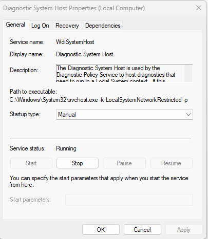
During normal operation, WDI periodically performs background RPC calls to the Remote Desktop service (TermService) using a high impersonation level. These RPC interactions occur automatically every 5–15 minutes and do not require any user input.

This behavior can be abused in a similar manner to the previous attack scenarios, as illustrated in the figure below.

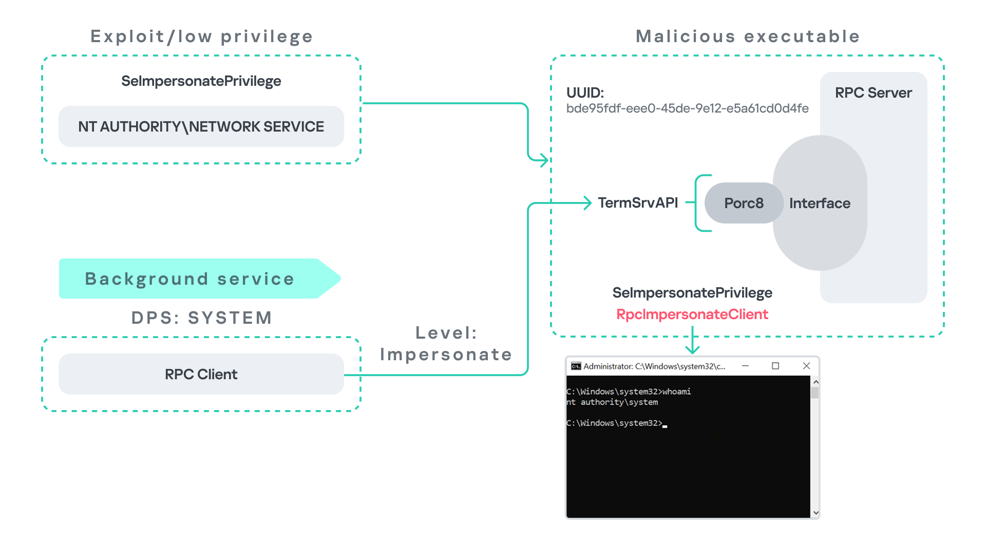
In this case, however, no user interaction or coercion is required. After deploying a malicious RPC server that mimics the expected TermService RPC interface, the attacker only needs to wait for the WDI service to perform its periodic RPC call. Because the request is made with a high impersonation level, the malicious server can invoke RpcImpersonateClient and impersonate the calling process. This enables the attacker to escalate privileges to SYSTEM.

Abusing the Local Service account: From ipconfig to DHCP

Another scenario involves the DHCP Client service, which manages DHCP client operations on Windows systems. This service runs under the Local Service account and is enabled by default.

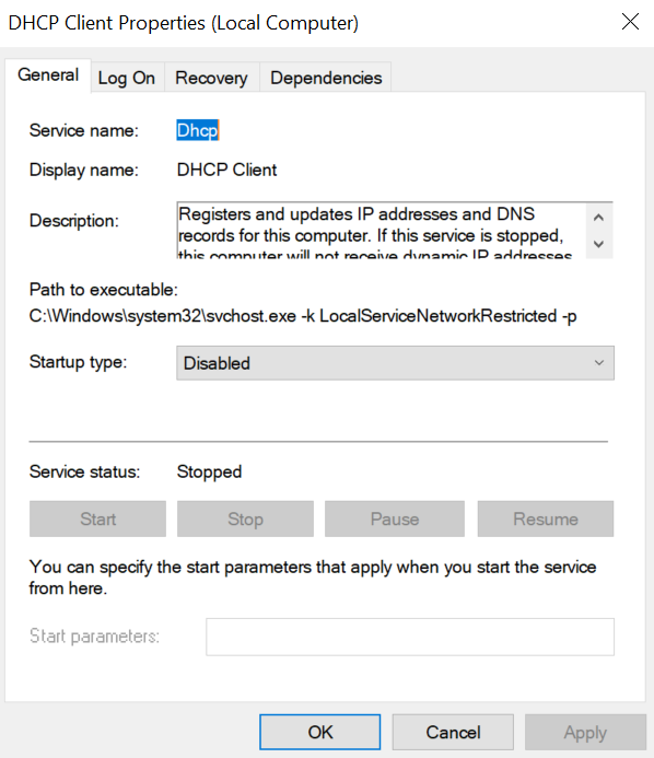
The DHCP Client service exposes an RPC server with multiple interfaces and endpoints. These interfaces are frequently invoked by various system DLLs, often using a high impersonation level.

In this scenario, instead of compromising a process running under Network Service, it is assumed the attacker has compromised a process running under the Local Service account. I also assume that the DHCP Client service is disabled, meaning the legitimate RPC server is unavailable.

As the figure below illustrates, the attacker can leverage this situation to escalate privileges.

After gaining control of a Local Service process, the attacker deploys a malicious RPC server that mimics the legitimate RPC server normally exposed by the DHCP Client service. Once the malicious server is running, the attacker waits for a high-privileged user, such as an administrator, to execute ipconfig.exe.

When ipconfig is run, it internally triggers an RPC request to the DHCP Client service. Since the legitimate RPC server is not running, the request is received by the attacker’s fake RPC server. Because the RPC call is performed with a high impersonation level, the malicious server can call RpcImpersonateClient to impersonate the client.

As a result, the attacker can escalate privileges from the Local Service account to the Administrator account.

Abusing Time

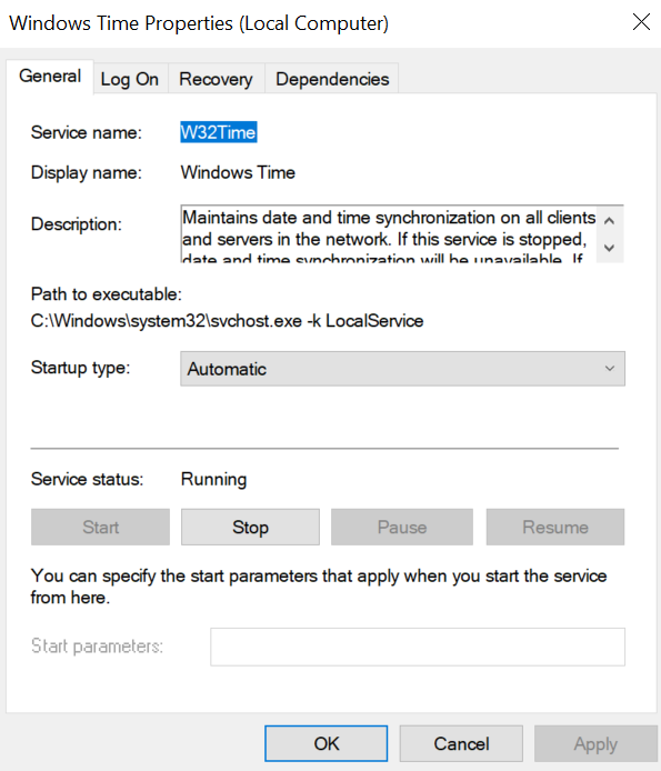
The Windows Time service (W32Time) is responsible for maintaining date and time synchronization across systems in a Windows environment. This service is enabled by default and runs under the Local Service account.

The service exposes an RPC server with two endpoints:

  • \PIPE\W32TIME_ALT
  • \RPC Control\W32TIME_ALT

The executable C:\Windows\System32\w32tm.exe interacts with the Windows Time service through RPC. However, before connecting to the valid RPC endpoints exposed by the service, the executable first attempts to access the nonexistent named pipe: \PIPE\W32TIME. This named pipe is not exposed by the legitimate W32Time service. However, if this endpoint were available, w32tm.exe would attempt to connect to it.

An attacker can abuse this behavior by deploying a malicious RPC server that mimics the legitimate RPC interface of the Windows Time service. Rather than exposing the legitimate endpoints, the attacker’s server exposes the nonexistent endpoint \PIPE\W32TIME, as shown in the figure below.

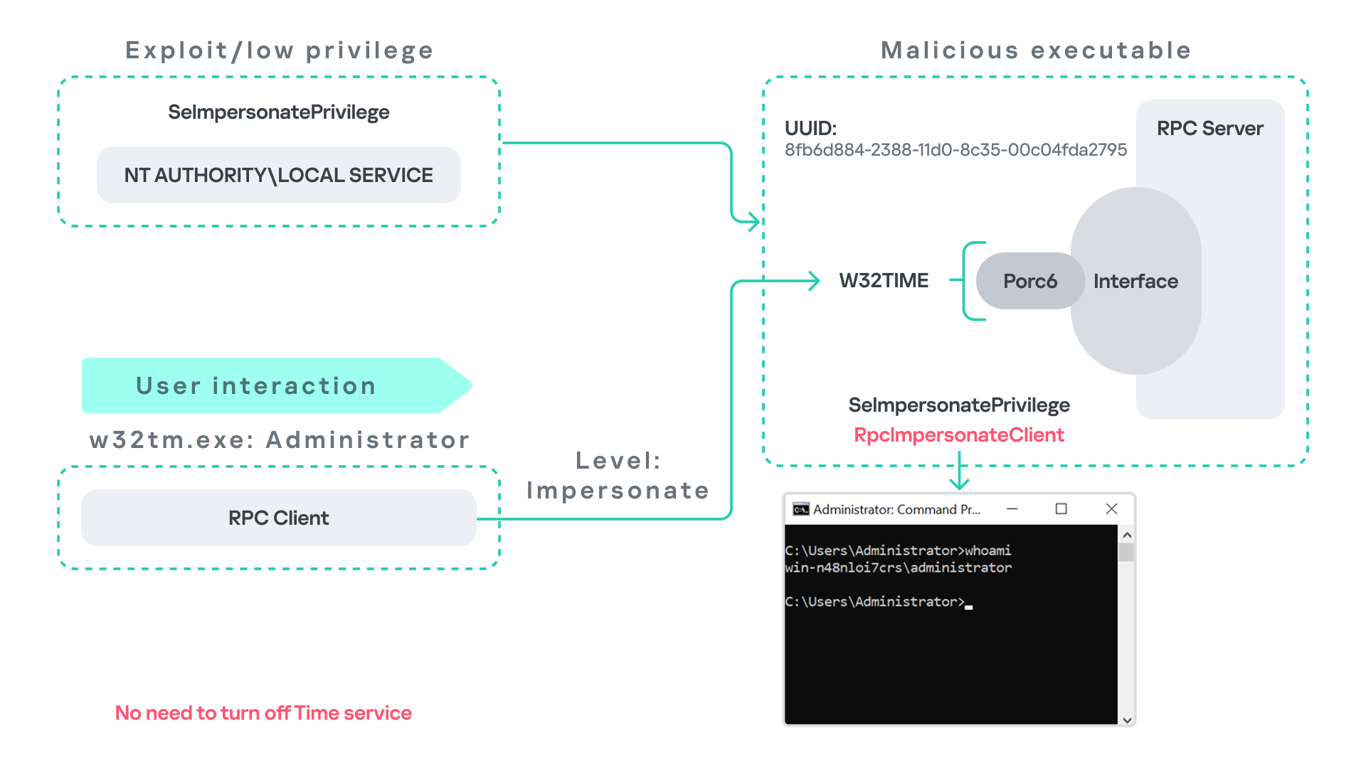
As in the previous scenarios, it is assumed the attacker has already compromised a process running under the Local Service account. The attacker then deploys a fake RPC server that implements the same RPC interface as the Windows Time service, but which exposes the alternative endpoint used by w32tm.exe.

Once the malicious server is running, the attacker simply waits for a high-privileged user, such as an administrator, to execute w32tm.exe. When the executable runs, it attempts to connect to the endpoint \PIPE\W32TIME. Because the attacker’s fake server exposes this endpoint, the RPC request is directed to the malicious server.

Since the RPC call is performed with a high impersonation level, the malicious server can impersonate the calling client. As a result, the attacker can escalate privileges from the Local Service account to the Administrator account.

In this scenario, it is important to note that the legitimate Windows Time service does not need to be disabled. Because the executable attempts to connect to a nonexistent endpoint, it is sufficient for the attacker to expose that endpoint through the malicious RPC server.

Vulnerability disclosure

After discovering the vulnerability, Kaspersky Security Services prepared a 10-page technical report describing the issue and the various aforementioned exploitation scenarios. The report was submitted to the Microsoft Security Response Center (MSRC) to report the vulnerability and request a fix.

Twenty days later, Microsoft responded, indicating that they did not classify the vulnerability as high severity. According to their assessment, the issue was classified as moderate severity and would therefore not be patched immediately. No CVE would be assigned, and the case would be closed without further tracking.

Microsoft explained that the moderate severity classification was due to the requirement that the originating process had to already possess the SeImpersonatePrivilege privilege. Since this privilege was typically required for the attack to succeed, Microsoft determined that the issue did not require immediate remediation.

Kaspersky Security Services respect Microsoft’s assessment and only published the research after the embargo period ends. In line with the coordinated vulnerability disclosure policy, Kaspersky Security Services will refrain from publishing detailed instructions that could enable or accelerate mass exploitation.

The disclosure timeline is shown below:

  • 2025-09-19: Vulnerability reported to Microsoft Security Response Center (Case 101749).
  • 2025-10-10: MSRC response – the case was assessed as moderate severity, not eligible for a bounty, no CVE was issued, and the case was closed without further tracking.
  • 2026-04-24: expected whitepaper publication date.

Detection and defense

As discussed above, this vulnerability is related to an architectural design behavior. Fully preventing it would require Microsoft to release a patch that addresses the underlying issue.

Nevertheless, organizations can still take steps to detect and mitigate potential abuse. ETW-based monitoring within the framework described above enables defenders to identify RPC exceptions in their environment, especially when RPC clients attempt to connect to unavailable servers.

I have provide the tools used in the previously described framework so that organizations can check their environment for such behavior. You can find all of them in the research repository.

By monitoring these events, administrators can identify situations where legitimate RPC servers are expected but not running. In some cases, the attack surface may be reduced by enabling the corresponding services, ensuring that the legitimate RPC server is available. This can hinder attackers from deploying malicious RPC servers that imitate legitimate endpoints.

It is also good practice to reduce the use of the SeImpersonatePrivilege privilege in processes where it is not required. Some system processes need this privilege for normal operations. However, granting it to custom processes is generally not considered good security practice.

Conclusion

All the exploits described in this research were tested on Windows Server 2022 and Windows Server 2025 with the latest available updates prior to the submission date. The proof-of-concept implementations can be found in the research repository. However, it is highly likely that this issue may also be exploitable on other Windows versions.

Because the vulnerability stems from an architectural design issue, there may be additional attack scenarios beyond those presented in this research. The exact exploitation paths may vary from one system to another depending on factors such as installed software, the DLLs involved in RPC communication, and the availability of corresponding RPC servers.

  • ✇Securelist
  • Yet another DCOM object for lateral movement Haidar Kabibo
    Introduction If you’re a penetration tester, you know that lateral movement is becoming increasingly difficult, especially in well-defended environments. One common technique for remote command execution has been the use of DCOM objects. Over the years, many different DCOM objects have been discovered. Some rely on native Windows components, others depend on third-party software such as Microsoft Office, and some are undocumented objects found through reverse engineering. While certain objects s
     

Yet another DCOM object for lateral movement

19 de Dezembro de 2025, 05:00

Introduction

If you’re a penetration tester, you know that lateral movement is becoming increasingly difficult, especially in well-defended environments. One common technique for remote command execution has been the use of DCOM objects.

Over the years, many different DCOM objects have been discovered. Some rely on native Windows components, others depend on third-party software such as Microsoft Office, and some are undocumented objects found through reverse engineering. While certain objects still work, others no longer function in newer versions of Windows.

This research presents a previously undescribed DCOM object that can be used for both command execution and potential persistence. This new technique abuses older initial access and persistence methods through Control Panel items.

First, we will discuss COM technology. After that, we will review the current state of the Impacket dcomexec script, focusing on objects that still function, and discuss potential fixes and improvements, then move on to techniques for enumerating objects on the system. Next, we will examine Control Panel items, how adversaries have used them for initial access and persistence, and how these items can be leveraged through a DCOM object to achieve command execution.

Finally, we will cover detection strategies to identify and respond to this type of activity.

COM/DCOM technology

What is COM?

COM stands for Component Object Model, a Microsoft technology that defines a binary standard for interoperability. It enables the creation of reusable software components that can interact at runtime without the need to compile COM libraries directly into an application.

These software components operate in a client–server model. A COM object exposes its functionality through one or more interfaces. An interface is essentially a collection of related member functions (methods).

COM also enables communication between processes running on the same machine by using local RPC (Remote Procedure Call) to handle cross-process communication.

Terms

To ensure a better understanding of its structure and functionality, let’s revise COM-related terminology.

  1. COM interface
    A COM interface defines the functionality that a COM object exposes. Each COM interface is identified by a unique GUID known as the IID (Interface ID). All COM interfaces can be found in the Windows Registry under HKEY_CLASSES_ROOT\Interface, where they are organized by GUID.
  2. COM class (COM CoClass)
    A COM class is the actual implementation of one or more COM interfaces. Like COM interfaces, classes are identified by unique GUIDs, but in this case the GUID is called the CLSID (Class ID). This GUID is used to locate the COM server and activate the corresponding COM class.

    All COM classes must be registered in the registry under HKEY_CLASSES_ROOT\CLSID, where each class’s GUID is stored. Under each GUID, you may find multiple subkeys that serve different purposes, such as:

    • InprocServer32/LocalServer32: Specifies the system path of the COM server where the class is defined. InprocServer32 is used for in-process servers (DLLs), while LocalServer32 is used for out-of-process servers (EXEs). We’ll describe this in more detail later.
    • ProgID: A human-readable name assigned to the COM class.
    • TypeLib: A binary description of the COM class (essentially documentation for the class).
    • AppID: Used to describe security configuration for the class.
  3. COM server
    A COM is the module where a COM class is defined. The server can be implemented as an EXE, in which case it is called an out-of-process server, or as a DLL, in which case it is called an in-process server. Each COM server has a unique file path or location in the system. Information about COM servers is stored in the Windows Registry. The COM runtime uses the registry to locate the server and perform further actions. Registry entries for COM servers are located under the HKEY_CLASSES_ROOT root key for both 32- and 64-bit servers.
Component Object Model implementation

Component Object Model implementation

Client–server model

  1. In-process server
    In the case of an in-process server, the server is implemented as a DLL. The client loads this DLL into its own address space and directly executes functions exposed by the COM object. This approach is efficient since both client and server run within the same process.
    In-process COM server

    In-process COM server

  2. Out-of-process server
    Here, the server is implemented and compiled as an executable (EXE). Since the client cannot load an EXE into its address space, the server runs in its own process, separate from the client. Communication between the two processes is handled via ALPC (Advanced Local Procedure Call) ports, which serve as the RPC transport layer for COM.
Out-of-process COM server

Out-of-process COM server

What is DCOM?

DCOM is an extension of COM where the D stands for Distributed. It enables the client and server to reside on different machines. From the user’s perspective, there is no difference: DCOM provides an abstraction layer that makes both the client and the server appear as if they are on the same machine.

Under the hood, however, COM uses TCP as the RPC transport layer to enable communication across machines.

Distributed COM implementation

Distributed COM implementation

Certain requirements must be met to extend a COM object into a DCOM object. The most important one for our research is the presence of the AppID subkey in the registry, located under the COM CLSID entry.

The AppID value contains a GUID that maps to a corresponding key under HKEY_CLASSES_ROOT\AppID. Several subkeys may exist under this GUID. Two critical ones are:

  • AccessPermission: controls access permissions.
  • LaunchPermission: controls activation permissions.

These registry settings grant remote clients permissions to activate and interact with DCOM objects.

Lateral movement via DCOM

After attackers compromise a host, their next objective is often to compromise additional machines. This is what we call lateral movement. One common lateral movement technique is to achieve remote command execution on a target machine. There are many ways to do this, one of which involves abusing DCOM objects.

In recent years, many DCOM objects have been discovered. This research focuses on the objects exposed by the Impacket script dcomexec.py that can be used for command execution. More specifically, three exposed objects are used: ShellWindows, ShellBrowserWindow and MMC20.

  1. ShellWindows
    ShellWindows was one of the first DCOM objects to be identified. It represents a collection of open shell windows and is hosted by explorer.exe, meaning any COM client communicates with that process.

    In Impacket’s dcomexec.py, once an instance of this COM object is created on a remote machine, the script provides a semi-interactive shell.

    Each time a user enters a command, the function exposed by the COM object is called. The command output is redirected to a file, which the script retrieves via SMB and displays back to simulate a regular shell.

    Internally, the script runs this command when connecting:

    cmd.exe /Q /c cd \ 1> \\127.0.0.1\ADMIN$\__17602 2>&1

    This sets the working directory to C:\ and redirects the output to the ADMIN$ share under the filename __17602. After that, the script checks whether the file exists; if it does, execution is considered successful and the output appears as if in a shell.

    When running dcomexec.py against Windows 10 and 11 using the ShellWindows object, the script hangs after confirming SMB connection initialization and printing the SMB banner. As I mentioned in my personal blog post, it appears that this DCOM object no longer has permission to write to the ADMIN$ share. A simple fix is to redirect the output to a directory the DCOM object can write to, such as the Temp folder. The Temp folder can then be accessed under the same ADMIN$ share. A small change in the code resolves the issue. For example:

    OUTPUT_FILENAME = 'Temp\\__' + str(time.time())[:5]

  2. ShellBrowserWindow
    The ShellBrowserWindow object behaves almost identically to ShellWindows and exhibits the same behavior on Windows 10. The same workaround that we used for ShellWindows applies in this case. However, on Windows 11, this object no longer works for command execution.
  3. MMC20
    The MMC20.Application COM object is the automation interface for Microsoft Management Console (MMC). It exposes methods and properties that allow MMC snap-ins to be automated.

    This object has historically worked across all Windows versions. Starting with Windows Server 2025, however, attempting to use it triggers a Defender alert, and execution is blocked.

    As shown in earlier examples, the dcomexec.py script writes the command output to a file under ADMIN$, with a filename that begins with __:

    OUTPUT_FILENAME = '__' + str(time.time())[:5]

    Defender appears to check for files written under ADMIN$ that start with __, and when it detects one, it blocks the process and alerts the user. A quick fix is to simply remove the double underscores from the output filename.

    Another way to bypass this issue is to use the same workaround used for ShellWindows – redirecting the output to the Temp folder. The table below outlines the status of these objects across different Windows versions.

    Windows Server 2025 Windows Server 2022 Windows 11 Windows 10
    ShellWindows Doesn’t work Doesn’t work Works but needs a fix Works but needs a fix
    ShellBrowserWindow Doesn’t work Doesn’t work Doesn’t work Works but needs a fix
    MMC20 Detected by Defender Works Works Works

Enumerating COM/DCOM objects

The first step to identifying which DCOM objects could be used for lateral movement is to enumerate them. By enumerating, I don’t just mean listing the objects. Enumeration involves:

  • Finding objects and filtering specifically for DCOM objects.
  • Identifying their interfaces.
  • Inspecting the exposed functions.

Automating enumeration is difficult because most COM objects lack a type library (TypeLib). A TypeLib acts as documentation for an object: which interfaces it supports, which functions are exposed, and the definitions of those functions. Even when TypeLibs are available, manual inspection is often still required, as we will explain later.

There are several approaches to enumerating COM objects depending on their use cases. Next, we’ll describe the methods I used while conducting this research, taking into account both automated and manual methods.

  1. Automation using PowerShell
    In PowerShell, you can use .NET to create and interact with DCOM objects. Objects can be created using either their ProgID or CLSID, after which you can call their functions (as shown in the figure below).
    Shell.Application COM object function list in PowerShell

    Shell.Application COM object function list in PowerShell

    Under the hood, PowerShell checks whether the COM object has a TypeLib and implements the IDispatch interface. IDispatch enables late binding, which allows runtime dynamic object creation and function invocation. With these two conditions met, PowerShell can dynamically interact with COM objects at runtime.

    Our strategy looks like this:

    As you can see in the last box, we perform manual inspection to look for functions with names that could be of interest, such as Execute, Exec, Shell, etc. These names often indicate potential command execution capabilities.

    However, this approach has several limitations:

    • TypeLib requirement: Not all COM objects have a TypeLib, so many objects cannot be enumerated this way.
    • IDispatch requirement: Not all COM objects implement the IDispatch interface, which is required for PowerShell interaction.
    • Interface control: When you instantiate an object in PowerShell, you cannot choose which interface the instance will be tied to. If a COM class implements multiple interfaces, PowerShell will automatically select the one marked as [default] in the TypeLib. This means that other non-default interfaces, which may contain additional relevant functionality, such as command execution, could be overlooked.
  2. Automation using C++
    As you might expect, C++ is one of the languages that natively supports COM clients. Using C++, you can create instances of COM objects and call their functions via header files that define the interfaces.However, with this approach, we are not necessarily interested in calling functions directly. Instead, the goal is to check whether a specific COM object supports certain interfaces. The reasoning is that many interfaces have been found to contain functions that can be abused for command execution or other purposes.

    This strategy primarily relies on an interface called IUnknown. All COM interfaces should inherit from this interface, and all COM classes should implement it.The IUnknown interface exposes three main functions. The most important is QueryInterface(), which is used to ask a COM object for a pointer to one of its interfaces.So, the strategy is to:

    • Enumerate COM classes in the system by reading CLSIDs under the HKEY_CLASSES_ROOT\CLSID key.
    • Check whether they support any known valuable interfaces. If they do, those classes may be leveraged for command execution or other useful functionality.

    This method has several advantages:

    • No TypeLib dependency: Unlike PowerShell, this approach does not require the COM object to have a TypeLib.
    • Use of IUnknown: In C++, you can use the QueryInterface function from the base IUnknown interface to check if a particular interface is supported by a COM class.
    • No need for interface definitions: Even without knowing the exact interface structure, you can obtain a pointer to its virtual function table (vtable), typically cast as a void*. This is enough to confirm the existence of the interface and potentially inspect it further.

    The figure below illustrates this strategy:

    This approach is good in terms of automation because it eliminates the need for manual inspection. However, we are still only checking well-known interfaces commonly used for lateral movement, while potentially missing others.

  3. Manual inspection using open-source tools

    As you can see, automation can be difficult since it requires several prerequisites and, in many cases, still ends with a manual inspection. An alternative approach is manual inspection using a tool called OleViewDotNet, developed by James Forshaw. This tool allows you to:
    • List all COM classes in the system.
    • Create instances of those classes.
    • Check their supported interfaces.
    • Call specific functions.
    • Apply various filters for easier analysis.
    • Perform other inspection tasks.
    Open-source tool for inspecting COM interfaces

    Open-source tool for inspecting COM interfaces

    One of the most valuable features of this tool is its naming visibility. OleViewDotNet extracts the names of interfaces and classes (when available) from the Windows Registry and displays them, along with any associated type libraries.

    This makes manual inspection easier, since you can analyze the names of classes, interfaces, or type libraries and correlate them with potentially interesting functionality, for example, functions that could lead to command execution or persistence techniques.

Control Panel items as attack surfaces

Control Panel items allow users to view and adjust their computer settings. These items are implemented as DLLs that export the CPlApplet function and typically have the .cpl extension. Control Panel items can also be executables, but our research will focus on DLLs only.

Control Panel items

Control Panel items

Attackers can abuse CPL files for initial access. When a user executes a malicious .cpl file (e.g., delivered via phishing), the system may be compromised – a technique mapped to MITRE ATT&CK T1218.002.

Adversaries may also modify the extensions of malicious DLLs to .cpl and register them in the corresponding locations in the registry.

  • Under HKEY_CURRENT_USER:
    HKCU\Software\Microsoft\Windows\CurrentVersion\Control Panel\Cpls
  • Under HKEY_LOCAL_MACHINE:
    • For 64-bit DLLs:
      HKLM\Software\Microsoft\Windows\CurrentVersion\Control Panel\Cpls
    • For 32-bit DLLs:
      HKLM\Software\WOW6432Node\Microsoft\Windows\CurrentVersion\Control Panel\Cpls

These locations are important when Control Panel DLLs need to be available to the current logged-in user or to all users on the machine. However, the “Control Panel” subkey and its “Cpls” subkey under HKCU should be created manually, unlike the “Control Panel” and “Cpls” subkeys under HKLM, which are created automatically by the operating system.

Once registered, the DLL (CPL file) will load every time the Control Panel is opened, enabling persistence on the victim’s system.

It’s worth noting that even DLLs that do not comply with the CPL specification, do not export CPlApplet, or do not have the .cpl extension can still be executed via their DllEntryPoint function if they are registered under the registry keys listed above.

There are multiple ways to execute Control Panel items:

  • From cmd: control.exe [filename].cpl
  • By double-clicking the .cpl file.

Both methods use rundll32.exe under the hood:

rundll32.exe shell32.dll,Control_RunDLL [filename].cpl

This calls the Control_RunDLL function from shell32.dll, passing the CPL file as an argument. Everything inside the CPlApplet function will then be executed.

However, if the CPL file has been registered in the registry as shown earlier, then every time the Control Panel is opened, the file is loaded into memory through the COM Surrogate process (dllhost.exe):

COM Surrogate process loading the CPL file

COM Surrogate process loading the CPL file

What happened was that a Control Panel with a COM client used a COM object to load these CPL files. We will talk about this COM object in more detail later.

The COM Surrogate process was designed to host COM server DLLs in a separate process rather than loading them directly into the client process’s address space. This isolation improves stability for the in-process server model. This hosting behavior can be configured for a COM object in the registry if you want a COM server DLL to run inside a separate process because, by default, it is loaded in the same process.

‘DCOMing’ through Control Panel items

While following the manual approach of enumerating COM/DCOM objects that could be useful for lateral movement, I came across a COM object called COpenControlPanel, which is exposed through shell32.dll and has the CLSID {06622D85-6856-4460-8DE1-A81921B41C4B}. This object exposes multiple interfaces, one of which is IOpenControlPanel with IID {D11AD862-66DE-4DF4-BF6C-1F5621996AF1}.

IOpenControlPanel interface in the OleViewDotNet output

IOpenControlPanel interface in the OleViewDotNet output

I immediately thought of its potential to compromise Control Panel items, so I wanted to check which functions were exposed by this interface. Unfortunately, neither the interface nor the COM class has a type library.

COpenControlPanel interfaces without TypeLib

COpenControlPanel interfaces without TypeLib

Normally, checking the interface definition would require reverse engineering, so at first, it looked like we needed to take a different research path. However, it turned out that the IOpenControlPanel interface is documented on MSDN, and according to the documentation, it exposes several functions. One of them, called Open, allows a specified Control Panel item to be opened using its name as the first argument.

Full type and function definitions are provided in the shobjidl_core.h Windows header file.

Open function exposed by IOpenControlPanel interface

Open function exposed by IOpenControlPanel interface

It’s worth noting that in newer versions of Windows (e.g., Windows Server 2025 and Windows 11), Microsoft has removed interface names from the registry, which means they can no longer be identified through OleViewDotNet.

COpenControlPanel interfaces without names

COpenControlPanel interfaces without names

Returning to the COpenControlPanel COM object, I found that the Open function can trigger a DLL to be loaded into memory if it has been registered in the registry. For the purposes of this research, I created a DLL that basically just spawns a message box which is defined under the DllEntryPoint function. I registered it under HKCU\Software\Microsoft\Windows\CurrentVersion\Control Panel\Cpls and then created a simple C++ COM client to call the Open function on this interface.

As expected, the DLL was loaded into memory. It was hosted in the same way that it would be if the Control Panel itself was opened: through the COM Surrogate process (dllhost.exe). Using Process Explorer, it was clear that dllhost.exe loaded my DLL while simultaneously hosting the COpenControlPanel object along with other COM objects.

COM Surrogate loading a custom DLL and hosting the COpenControlPanel object

COM Surrogate loading a custom DLL and hosting the COpenControlPanel object

Based on my testing, I made the following observations:

  1. The DLL that needs to be registered does not necessarily have to be a .cpl file; any DLL with a valid entry point will be loaded.
  2. The Open() function accepts the name of a Control Panel item as its first argument. However, it appears that even if a random string is supplied, it still causes all DLLs registered in the relevant registry location to be loaded into memory.

Now, what if we could trigger this COM object remotely? In other words, what if it is not just a COM object but also a DCOM object? To verify this, we checked the AppID of the COpenControlPanel object using OleViewDotNet.

COpenControlPanel object in OleViewDotNet

COpenControlPanel object in OleViewDotNet

Both the launch and access permissions are empty, which means the object will follow the system’s default DCOM security policy. By default, members of the Administrators group are allowed to launch and access the DCOM object.

Based on this, we can build a remote strategy. First, upload the “malicious” DLL, then use the Remote Registry service to register it in the appropriate registry location. Finally, use a trigger acting as a DCOM client to remotely invoke the Open() function, causing our DLL to be loaded. The diagram below illustrates the flow of this approach.

Malicious DLL loading using DCOM

Malicious DLL loading using DCOM

The trigger can be written in either C++ or Python, for example, using Impacket. I chose Python because of its flexibility. The trigger itself is straightforward: we define the DCOM class, the interface, and the function to call. The full code example can be found here.

Once the trigger runs, the behavior will be the same as when executing the COM client locally: our DLL will be loaded through the COM Surrogate process (dllhost.exe).

As you can see, this technique not only achieves command execution but also provides persistence. It can be triggered in two ways: when a user opens the Control Panel or remotely at any time via DCOM.

Detection

The first step in detecting such activity is to check whether any Control Panel items have been registered under the following registry paths:

  • HKCU\Software\Microsoft\Windows\CurrentVersion\Control Panel\Cpls
  • HKLM\Software\Microsoft\Windows\CurrentVersion\Control Panel\Cpls
  • HKLM\Software\WOW6432Node\Microsoft\Windows\CurrentVersion\Control Panel\Cpls

Although commonly known best practices and research papers regarding Windows security advise monitoring only the first subkey, for thorough coverage it is important to monitor all of the above.

In addition, monitoring dllhost.exe (COM Surrogate) for unusual COM objects such as COpenControlPanel can provide indicators of malicious activity.
Finally, it is always recommended to monitor Remote Registry usage because it is commonly abused in many types of attacks, not just in this scenario.

Conclusion

In conclusion, I hope this research has clarified yet another attack vector and emphasized the importance of implementing hardening practices. Below are a few closing points for security researchers to take into account:

  • As shown, DCOM represents a large attack surface. Windows exposes many DCOM classes, a significant number of which lack type libraries – meaning reverse engineering can reveal additional classes that may be abused for lateral movement.
  • Changing registry values to register malicious CPLs is not good practice from a red teaming ethics perspective. Defender products tend to monitor common persistence paths, but Control Panel applets can be registered in multiple registry locations, so there is always a gap that can be exploited.
  • Bitness also matters. On x64 systems, loading a 32-bit DLL will spawn a 32-bit COM Surrogate process (dllhost.exe *32). This is unusual on 64-bit hosts and therefore serves as a useful detection signal for defenders and an interesting red flag for red teamers to consider.

  • ✇Securelist
  • Turn me on, turn me off: Zigbee assessment in industrial environments Haidar Kabibo
    We all encounter IoT and home automation in some form or another, from smart speakers to automated sensors that control water pumps. These services appear simple and straightforward to us, but many devices and protocols work together under the hood to deliver them. One of those protocols is Zigbee. Zigbee is a low-power wireless protocol (based on IEEE 802.15.4) used by many smart devices to talk to each other. It’s common in homes, but is also used in industrial environments where hundreds or t
     

Turn me on, turn me off: Zigbee assessment in industrial environments

12 de Dezembro de 2025, 05:00

We all encounter IoT and home automation in some form or another, from smart speakers to automated sensors that control water pumps. These services appear simple and straightforward to us, but many devices and protocols work together under the hood to deliver them.

One of those protocols is Zigbee. Zigbee is a low-power wireless protocol (based on IEEE 802.15.4) used by many smart devices to talk to each other. It’s common in homes, but is also used in industrial environments where hundreds or thousands of sensors may coordinate to support a process.

There are many guides online about performing security assessments of Zigbee. Most focus on the Zigbee you see in home setups. They often skip the Zigbee used at industrial sites, what I call ‘non-public’ or ‘industrial’ Zigbee.

In this blog, I will take you on a journey through Zigbee assessments. I’ll explain the basics of the protocol and map the attack surface likely to be found in deployments. I’ll also walk you through two realistic attack vectors that you might see in facilities, covering the technical details and common problems that show up in assessments. Finally, I will present practical ways to address these problems.

Zigbee introduction

Protocol overview

Zigbee is a wireless communication protocol designed for low-power applications in wireless sensor networks. Based on the IEEE 802.15.4 standard, it was created for short-range and low-power communication. Zigbee supports mesh networking, meaning devices can connect through each other to extend the network range. It operates on the 2.4 GHz frequency band and is widely used in smart homes, industrial automation, energy monitoring, and many other applications.

You may be wondering why there’s a need for Zigbee when Wi-Fi is everywhere? The answer depends on the application. In most home setups, Wi-Fi works well for connecting devices. But imagine you have a battery-powered sensor that isn’t connected to your home’s electricity. If it used Wi-Fi, its battery would drain quickly – maybe in just a few days – because Wi-Fi consumes much more power. In contrast, the Zigbee protocol allows for months or even years of uninterrupted work.

Now imagine an even more extreme case. You need to place sensors in a radiation zone where humans can’t go. You drop the sensors from a helicopter and they need to operate for months without a battery replacement. In this situation, power consumption becomes the top priority. Wi-Fi wouldn’t work, but Zigbee is built exactly for this kind of scenario.

Also, Zigbee has a big advantage if the area is very large, covering thousands of square meters and requiring thousands of sensors: it supports thousands of nodes in a mesh network, while Wi-Fi is usually limited to hundreds at most.

There are lots more ins and outs, but these are the main reasons Zigbee is preferred for large-scale, low-power sensor networks.

Since both Zigbee and IEEE 802.15.4 define wireless communication, many people confuse the two. The difference between them, to put it simply, concerns the layers they support. IEEE 802.15.4 defines the physical (PHY) and media access control (MAC) layers, which basically determine how devices send and receive data over the air. Zigbee (as well as other protocols like Thread, WirelessHART, 6LoWPAN, and MiWi) builds on IEEE 802.15.4 by adding the network and application layers that define how devices form a network and communicate.

Zigbee operates in the 2.4 GHz wireless band, which it shares with Wi-Fi and Bluetooth. The Zigbee band includes 16 channels, each with a 2 MHz bandwidth and a 5 MHz gap between channels.

This shared frequency means Zigbee networks can sometimes face interference from Wi-Fi or Bluetooth devices. However, Zigbee’s low power and adaptive channel selection help minimize these conflicts.

Devices and network

There are three main types of Zigbee devices, each of which plays a different role in the network.

  1. Zigbee coordinator
    The coordinator is the brain of the Zigbee network. A Zigbee network is always started by a coordinator and can only contain one coordinator, which has the fixed address 0x0000.
    It performs several key tasks:
    • Starts and manages the Zigbee network.
    • Chooses the Zigbee channel.
    • Assigns addresses to other devices.
    • Stores network information.
    • Chooses the PAN ID: a 2-byte identifier (for example, 0x1234) that uniquely identifies the network.
    • Sets the Extended PAN ID: an 8-byte value, often an ASCII name representing the network.

    The coordinator can have child devices, which can be either Zigbee routers or Zigbee end devices.

  2. Zigbee router
    The router works just like a router in a traditional network: it forwards data between devices, extends the network range and can also accept child devices, which are usually Zigbee end devices.
    Routers are crucial for building large mesh networks because they enable communication between distant nodes by passing data through multiple hops.
  3. Zigbee end device
    The end device, also referred to as a Zigbee endpoint, is the simplest and most power-efficient type of Zigbee device. It only communicates with its parent, either a coordinator or router, and sleeps most of the time to conserve power. Common examples include sensors, remotes, and buttons.

Zigbee end devices do not accept child devices unless they are configured as both a router and an endpoint simultaneously.

Each of these device types, also known as Zigbee nodes, has two types of address:

  • Short address: two bytes long, similar to an IP address in a TCP/IP network.
  • Extended address: eight bytes long, similar to a MAC address.

Both addresses can be used in the MAC and network layers, unlike in TCP/IP, where the MAC address is used only in Layer 2 and the IP address in Layer 3.

Zigbee setup

Zigbee has many attack surfaces, such as protocol fuzzing and low-level radio attacks. In this post, however, I’ll focus on application-level attacks. Our test setup uses two attack vectors and is intentionally small to make the concepts clear.

In our setup, a Zigbee coordinator is connected to a single device that functions as both a Zigbee endpoint and a router. The coordinator also has other interfaces (Ethernet, Bluetooth, Wi-Fi, LTE), while the endpoint has a relay attached that the coordinator can switch on or off over Zigbee. This relay can be triggered by events coming from any interface, for example, a Bluetooth command or an Ethernet message.

Our goal will be to take control of the relay and toggle its state (turn it off and on) using only the Zigbee interface. Because the other interfaces (Ethernet, Bluetooth, Wi-Fi, LTE) are out of scope, the attack must work by hijacking Zigbee communication.

For the purposes of this research, we will attempt to hijack the communication between the endpoint and the coordinator. The two attack vectors we will test are:

  1. Spoofed packet injection: sending forged Zigbee commands made to look like they come from the coordinator to trigger the relay.
  2. Coordinator impersonation (rejoin attack): impersonating the legitimate coordinator to trick the endpoint into joining the attacker-controlled coordinator and controlling it directly.

Spoofed packet injection

In this scenario, we assume the Zigbee network is already up and running and that both the coordinator and endpoint nodes are working normally. The coordinator has additional interfaces, such as Ethernet, and the system uses those interfaces to trigger the relay. For instance, a command comes in over Ethernet and the coordinator sends a Zigbee command to the endpoint to toggle the relay. Our goal is to toggle the relay by injecting simulated legitimate Zigbee packets, using only the Zigbee link.

Sniffing

The first step in any radio assessment is to sniff the wireless traffic so we can learn how the devices talk. For Zigbee, a common and simple tool is the nRF52840 USB dongle by Nordic Semiconductor. With the official nRF Sniffer for 802.15.4 firmware, the dongle can run in promiscuous mode to capture all 802.15.4/Zigbee traffic. Those captures can be opened in Wireshark with the appropriate dissector to inspect the frames.

How do you find the channel that’s in use?

Zigbee runs on one of the 16 channels that we mentioned earlier, so we must set the sniffer to the same channel that the network uses. One practical way to scan the channels is to change the sniffer channel manually in Wireshark and watch for Zigbee traffic. When we see traffic, we know we’ve found the right channel.

After selecting the channel, we will be able to see the communication between the endpoint and the coordinator, though it will most likely be encrypted:

In the “Info” column, we can see that Wireshark only identifies packets as Data or Command without specifying their exact type, and that’s because the traffic is encrypted.

Even when Zigbee payloads are encrypted, the network and MAC headers remain visible. That means we can usually read things like source and destination addresses, PAN ID, short and extended MAC addresses, and frame control fields. The application payload (i.e., the actual command to toggle the relay) is typically encrypted at the Zigbee network/application layer, so we won’t see it in clear text without encryption keys. Nevertheless, we can still learn enough from the headers.

Decryption

Zigbee supports several key types and encryption models. In this post, we’ll keep it simple and look at a case involving only two security-related devices: a Zigbee coordinator and a device that is both an endpoint and a router. That way, we’ll only use a network encryption model, whereas with, say, mesh networks there can be various encryption models in use.

The network encryption model is a common concept. The traffic that we sniffed earlier is typically encrypted using the network key. This key is a symmetric AES-128 key shared by all devices in a Zigbee network. It protects network-layer packets (hop-by-hop) such as routing and broadcast packets. Because every router on the path shares the network key, this encryption method is not considered end-to-end.

Depending on the specific implementation, Zigbee can use two approaches for application payloads:

  • Network-layer encryption (hop-by-hop): the network key encrypts the Application Support Sublayer (APS) data, the sublayer of the application layer in Zigbee. In this case, each router along the route can decrypt the APS payload. This is not end-to-end encryption, so it is not recommended for transmitting sensitive data.
  • Link key (end-to-end) encryption: a link key, which is also an AES-128 key, is shared between two devices (for example, the coordinator and an endpoint).

The link key provides end-to-end protection of the APS payload between the two devices.

Because the network key could allow an attacker to read and forge many types of network traffic, it must be random and protected. Exposing the key effectively compromises the entire network.

When a new device joins, the coordinator (Trust Center) delivers the network key using a Transport Key command. That transport packet must be protected by a link key so the network key is not exposed in clear text. The link key authenticates the joining device and protects the key delivery.

The image below shows the transport packet:

There are two common ways link keys are provided:

  • Pre-installed: the device ships with an installation code or link key already set.
  • Key establishment: the device runs a key-establishment protocol.

A common historical problem is the global default Trust Center link key, “ZigBeeAlliance09”. It was included in early versions of Zigbee (pre-3.0) to facilitate testing and interoperability. However, many vendors left it enabled on consumer devices, and that has caused major security issues. If an attacker knows this key, they can join devices and read or steal the network key.

Newer versions – Zigbee 3.0 and later – introduced installation codes and procedures to derive unique link keys for each device. An installation code is usually a factory-assigned secret (often encoded on the device label) that the Trust Center uses to derive a unique link key for the device in question. This helps avoid the problems caused by a single hard-coded global key.

Unfortunately, many manufacturers still ignore these best practices. During real assessments, we often encounter devices that use default or hard-coded keys.

How can these keys be obtained?

If an endpoint has already joined the network and communicates with the coordinator using the network key, there are two main options for decrypting traffic:

  1. Guess or brute-force the network key. This is usually impractical because a properly generated network key is a random AES-128 key.
  2. Force the device to rejoin and capture the transport key. If we can make the endpoint leave the network and then rejoin, the coordinator will send the transport key. Capturing that packet can reveal the network key, but the transport key itself is protected by the link key. Therefore, we still need the link key.

To obtain the network and link keys, many approaches can be used:

  • The well-known default link key, ZigBeeAlliance09. Many legacy devices still use it.
  • Identify the device manufacturer and search for the default keys used by that vendor. We can find the manufacturer by:
    • Checking the device MAC/OUI (the first three bytes of the 64-bit extended address often map to a vendor).
    • Physically inspecting the device (label, model, chip markings).
  • Extract the firmware from the coordinator or device if we have physical access and search for hard-coded keys inside the firmware images.

Once we have the relevant keys, the decryption process is straightforward:

  1. Open the capture in Wireshark.
  2. Go to Edit -> Preferences -> Protocols -> Zigbee.
  3. Add the network key and any link keys in our possession.
  4. Wireshark will then show decrypted APS payloads and higher-level Zigbee packets.

After successful decryption, packet types and readable application commands will be visible, such as Link Status or on/off cluster commands:

Choose your gadget

Now that we can read and potentially decrypt traffic, we need hardware and software to inject packets over the Zigbee link between the coordinator and the endpoint. To keep this practical and simple, I opted for cheap, widely available tools that are easy to set up.

For the hardware, I used the nRF52840 USB dongle, the same device we used for sniffing. It’s inexpensive, easy to find, and supports IEEE 802.15.4/Zigbee, so it can sniff and transmit.

The dongle runs the firmware we can use. A good firmware platform is Zephyr RTOS. Zephyr has an IEEE 802.15.4 radio API that enables the device to receive raw frames, essentially enabling sniffer mode, as well as send raw frames as seen in the snippets below.

Using this API and other components, we created a transceiver implementation written in C, compiled it to firmware, and flashed it to the dongle. The firmware can expose a simple runtime interface, such as a USB serial port, which allows us to control the radio from a laptop.

At runtime, the dongle listens on the serial port (for example, /dev/ttyACM1). Using a script, we can send it raw bytes, which the firmware will pass to the radio API and transmit to the channel. The following is an example of a tiny Python script to open the serial port:

I used the Scapy tool with the 802.15.4/Zigbee extensions to build Zigbee packets. Scapy lets us assemble packets layer-by-layer – MAC → NWK → APS → ZCL – and then convert them to raw bytes to send to the dongle. We will talk about APS and ZCL in more detail later.

Here is an example of how we can use Scapy to craft an APS layer packet:

from scapy.layers.dot15d4 import Dot15d4, Dot15d4FCS, Dot15d4Data, Dot15d4Cmd, Dot15d4Beacon, Dot15d4CmdAssocResp
from scapy.layers.zigbee import ZigbeeNWK, ZigbeeAppDataPayload, ZigbeeSecurityHeader, ZigBeeBeacon, ZigbeeAppCommandPayload

Before sending, the packet must be properly encrypted and signed so the endpoint accepts it. That means applying AES-CCM (AES-128 with MIC) using the network key (or the correct link key) and adhering to Zigbee’s rules for packet encryption and MIC calculation. This is how we implemented the encryption and MIC in Python (using a cryptographic library) after building the Scapy packet. We then sent the final bytes to the dongle.

This is how we implemented the encryption and MIC:

Crafting the packet

Now that we know how to inject packets, the next question is what to inject. To toggle the relay, we simply need to send the same type of command that the coordinator already sends. The easiest way to find that command is to sniff the traffic and read the application payload. However, when we look at captures in Wireshark, we can see many packets under ZCL marked [Malformed Packet].

A “malformed” ZCL packet usually means Wireshark could not fully interpret the packet because the application layer is non-standard or lacks details Wireshark expects. To understand why this happens, let’s look at the Zigbee application layer.

The Zigbee application layer consists of four parts:

  • Application Support Sublayer (APS): routes messages to the correct profile, endpoint, and cluster, and provides application-level security.
  • Application Framework (AF): contains the application objects that implement device functionality. These objects reside on endpoints (logical addresses 1–240) and expose clusters (sets of attributes and commands).
  • Zigbee Cluster Library (ZCL): defines standard clusters and commands so devices can interoperate.
  • Zigbee Device Object (ZDO): handles device discovery and management (out of scope for this post).

To make sense of application traffic, we must introduce three concepts:

  • Profile: a rulebook for how devices should behave for a specific use case. Public (standard) profiles are managed by the Connectivity Standards Alliance (CSA). Vendors can also create private profiles for proprietary features.
  • Cluster: a set of attributes and commands for a particular function. For example, the On/Off cluster contains On and Off commands and an OnOff attribute that displays the current state.
  • Endpoint: a logical “port” on the device where a profile and clusters reside. A device can host multiple endpoints for different functions.

Putting all this together, in the standard home automation traffic we see APS pointing to the home automation profile, the On/Off cluster, and a destination endpoint (for example, endpoint 1). In ZCL, the byte 0x00 often means “Off”.

In many industrial setups, vendors use private profiles or custom application frameworks. That’s why Wireshark can’t decode the packets; the AF payload is custom, so the dissector doesn’t know the format.

So how do we find the right bytes to toggle the switch when the application is private? Our strategy has two phases.

  1. Passive phase
    Sniff traffic while the system is driven legitimately. For example, trigger the relay from another interface (Ethernet or Bluetooth) and capture the Zigbee packets used to toggle the relay. If we can decrypt the captures, we can extract the application payload that correlates with the on/off action.
  2. Active phase
  3. With the legitimate payload at hand, we can now turn to creating our own packet. There are two ways to do that. First, we need to replay or duplicate the captured application payload exactly as it is. This works if there are no freshness checks like sequence numbers. Otherwise, we have to reverse-engineer the payload and adjust any counters or fields that prevent replay. For instance, many applications include an application-level counter. If the device ignores packets with a lower application counter, we must locate and increment that counter when we craft our packet.

    Another important protective measure is the frame counter inside the Zigbee security header (in the network header security fields). The frame counter prevents replay attacks; the receiver expects the frame counter to increase with each new packet, and will reject packets with a lower or repeated counter.

So, in the active phase, we must:

  1. Sniff the traffic until the coordinator sends a valid packet to the endpoint.
  2. Decrypt the packet, extract the counters and increase them by one.
  3. Build a packet with the correct APS/AF fields (profile, endpoint, cluster).
  4. Include a valid ZCL command or the vendor-specific payload that we identified in the passive phase.
  5. Encrypt and sign the packet with the correct network or link key.
  6. Make sure both the application counter (if used) and the Zigbee frame counter are modified so the packet is accepted.

The whole strategy for this phase will look like this:

If all of the above are handled correctly, we will be able to hijack the Zigbee communication and toggle the relay (turn it off and on) using only the Zigbee link.

Coordinator impersonation (rejoin attack)

The goal of this attack vector is to force the Zigbee endpoint to leave its original coordinator’s network and join our spoofed network so that we can take control of the device. To do this, we must achieve two things:

  1. Force the endpoint to leave the original network.
  2. Spoof the original coordinator and trick the node into joining our fake coordinator.

Force leaving

To better understand how to manipulate endpoint connections, let’s first describe the concept of a beacon frame. Beacon frames are periodic announcements sent by a coordinator and by routers. They advertise the presence of a network and provide join information, such as:

  • PAN ID and Extended PAN ID
  • Coordinator address
  • Stack/profile information
  • Device capacity (for example, whether the coordinator can accept child devices)

When a device wants to join, it sends a beacon request across Zigbee channels and waits for beacon replies from nearby coordinators/routers. Even if the network is not beacon-enabled for regular synchronization, beacon frames are still used during the join/discovery process, so they are mandatory when a node tries to discover networks.

Note that beacon frames exist at both the Zigbee and IEEE 802.15.4 levels. The MAC layer carries the basic beacon structure that Zigbee then extends with network-specific fields.

Now, we can force the endpoint to leave its network by abusing how Zigbee handles PAN conflicts. If a coordinator sees beacons from another coordinator using the same PAN ID and the same channel, it may trigger a PAN ID conflict resolution. When that happens, the coordinator can instruct its nodes to change PAN ID and rejoin, which causes them to leave and then attempt to join again. That rejoin window gives us an opportunity to advertise a spoofed coordinator and capture the joining node.

In the capture shown below, packet 7 is a beacon generated by our spoofed coordinator using the same PAN ID as the real network. As a result, the endpoint with the address 0xe8fa leaves the network (see packets 14–16).

Choose me

After forcing the endpoint to leave its original network by sending a fake beacon, the next step is to make the endpoint choose our spoofed coordinator. At this point, we assume we already have the necessary keys (network and link keys) and understand how the application behaves.

To impersonate the original coordinator, our spoofed coordinator must reply to any beacon request the endpoint sends. The beacon response must include the same Extended PAN ID (and other fields) that the endpoint expects. If the endpoint deems our beacon acceptable, it may attempt to join us.

I can think of two ways to make the endpoint prefer our coordinator.

  1. Jam the real coordinator
    Use a device that reduces the real coordinator’s signal at the endpoint so that it appears weaker, forcing the endpoint to prefer our beacon. This requires extra hardware.
  2. Exploit undefined or vendor-specific behavior
    Zigbee stacks sometimes behave slightly differently across vendors. One useful field in a beacon is the Update ID field. It increments when a coordinator changes network configuration.

If two coordinators advertise the same Extended PAN ID but one has a higher Update ID, some stacks will prefer the beacon with the higher Update ID. This is undefined behavior across implementations; it works on some stacks but not on others. In my experience, sometimes it works and sometimes it fails. There are lots of other similar quirks we can try during an assessment.

Even if the endpoint chooses our fake coordinator, the connection may be unstable. One main reason for that is the timing. The endpoint expects ACKs for the frames it sends to the coordinator, as well as fast responses regarding connection initiation packets. If our responder is implemented in Python on a laptop that receives packets, builds responses, and forwards them to a dongle, the round trip will be too slow. The endpoint will not receive timely ACKs or packets and will drop the connection.

In short, we’re not just faking a few packets; we’re trying to reimplement parts of Zigbee and IEEE 802.15.4 that must run quickly and reliably. This is usually too slow for production stacks when done in high-level, interpreted code.

A practical fix is to run a real Zigbee coordinator stack directly on the dongle. For example, the nRF52840 dongle can act as a coordinator if flashed with the right Nordic SDK firmware (see Nordic’s network coordinator sample). That provides the correct timing and ACK behavior needed for a stable connection.

However, that simple solution has one significant disadvantage. In industrial deployments we often run into incompatibilities. In my tests I compared beacons from the real coordinator and the Nordic coordinator firmware. Notable differences were visible in stack profile headers:

The stack profile identifies the network profile type. Common values include 0x00, which is a network-specific (private) profile, and 0x02, which is a Zigbee Pro (public) profile.

If the endpoint expects a network-specific profile (i.e., it uses a private vendor profile) and we provide Zigbee Pro, the endpoint will refuse to join. Devices that only understand private profiles will not join public-profile networks, and vice versa. In my case, I could not change the Nordic firmware to match the proprietary stack profile, so the endpoint refused to join.

Because of this discrepancy, the “flash a coordinator firmware on the dongle” fix was ineffective in that environment. This is why the standard off-the-shelf tools and firmware often fail in industrial cases, forcing us to continue working with and optimizing our custom setup instead.

Back to the roots

In our previous test setup we used a sniffer in promiscuous mode, which receives every frame on the air regardless of destination. Real Zigbee (IEEE 802.15.4) nodes do not work like that. At the MAC/802.15.4 layer, a node filters frames by PAN ID and destination address. A frame is only passed to upper layers if the PAN ID matches and the destination address is the node’s address or a broadcast address.

We can mimic that real behavior on the dongle by running Zephyr RTOS and making the dongle act as a basic 802.15.4 coordinator. In that role, we set a PAN ID and short network address on the dongle so that the radio only accepts frames that match those criteria. This is important because it allows the dongle to handle auto-ACKs and MAC-level timing: the dongle will immediately send ACKs at the MAC level.

With the dongle doing MAC-level work (sending ACKs and PAN filtering), we can implement the Zigbee logic in Python. Scapy helps a lot with packet construction: we can create our own beacons with the headers matching those of the original coordinator, which solves the incompatibility problem. However, we must still implement the higher-level Zigbee state machine in our code, including connection initiation, association, network key handling, APS/AF behavior, and application payload handling. That’s the hardest part.

There is one timing problem that we cannot solve in Python: the very first steps of initiating a connection require immediate packet responses. To handle this issue, we implemented the time-critical parts in C on the dongle firmware. For example, we can statically generate the packets for connection initiation in Python and hard-code them in the firmware. Then, using “if” statements, we can determine how to respond to each packet from the endpoint.

So, we let the dongle (C/Zephyr) handle MAC-level ACKs and the initial association handshake, but let Python build higher-level packets and instruct the dongle what to send next when dealing with the application level. This hybrid model reduces latency and maintains a stable connection. The final architecture looks like this:

Deliver the key

Here’s a quick recap of how joining works: a Zigbee endpoint broadcasts beacon requests across channels, waits for beacon responses, chooses a coordinator, and sends an association request, followed by a data request to identify its short address. The coordinator then sends a transport key packet containing the network key. If the endpoint has the correct link key, it can decrypt the transport key packet and obtain the network key, meaning it has now been authenticated. From that point on, network traffic is encrypted with the network key. The entire process looks like this:

The sticking point is the transport key packet. This packet is protected using the link key, a per-device key shared between the coordinator (Trust Center) and the joining endpoint. Before the link key can be used for encryption, it often needs to be processed (hashed/derived) according to Zigbee’s key derivation rules. Since there is no trivial Python implementation that implements this hashing algorithm, we may need to implement the algorithm ourselves.

I implemented the required key derivation; the code is available on our GitHub.

Now that we’ve managed to obtain the hashed link key and deliver it to the endpoint, we can successfully mimic a coordinator.

The final success

If we follow the steps above, we can get the endpoint to join our spoofed coordinator. Once the endpoint joins, it will often remain associated with our coordinator, even after we power it down (until another event causes it to re-evaluate its connection). From that point on, we can interact with the device at the application layer using Python. Getting access as a coordinator allowed us to switch the relay on and off as intended, but also provided much more functionality and control over the node.

Conclusion

In conclusion, this study demonstrates why private vendor profiles in industrial environments complicate assessments: common tools and frameworks often fail, necessitating the development of custom tools and firmware. We tested a simple two-node scenario, but with multiple nodes the attack surface changes drastically and new attack vectors emerge (for example, attacks against routing protocols).

As we saw, a misconfigured Zigbee setup can lead to a complete network compromise. To improve Zigbee security, use the latest specification’s security features, such as using installation codes to derive unique link keys for each device. Also, avoid using hard-coded or default keys. Finally, it is not recommended to use the network key encryption model. Add another layer of security in addition to the network level protection by using end-to-end encryption at the application level.

❌
❌